TOP
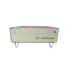
4083A(4061A) HP Switch Mainframe
Additional Features: Measurement Functions DC Current, DC Voltage, Capacitance and Conductance, Impedance and Differential voltage and Pulse force. DC Measurements Spot, Sweep, Pulse Bias, and Pulse Sweep. Measurement unit: HRSMU (High Resolution SMU), (Can be used only with ultra-low current matrix cards) MPSMU (Medium Power SMU and HPSMU (High Power SMU) Measurement range: 1 fA (Using HRSMU. Using MPSMU, 10 fA to 100 mA, 2 μV to 100 V) to 100 mA, 2 μV to 100 V (using the two low current SMU ports) 10 fA to 1 A (Using optional HPSMU. Using MPSMU, 10 fA to 100 mA, 2 μV to 100 V), 2 μV to 200 V (Using optional HPSMU. Using MPSMU, 10 fA to 100 mA, 2 μV to 100 V), (using the 6 standard SMU ports) Capacitance/Conductance Measurement Using Optional HS-CMU C/G, C/G -V, C/G -V/f Measurement unit: High Speed Capacitance Measurement Unit (HS-CMU) Measurement Frequencies: 1 kHz - 2 MHz, 34 points Measurement range: 1 fF to 100 nF, 0.1 nS to 7.5 mS DC Bias Voltage: ±10 V Impedance Measurements Using Optional HS-CMU Z/PHASE and Z/PHASE - f Measurement unit: HS-CMU Measurement Frequencies: 1 kHz - 2 MHz, 34 points DC Bias Voltage: ±10 V Capacitance/Conductance Measurements Using Optional Agilent E4980A LCR Meter Measurements: C/G and C/G-V Measurement unit: Agilent E4980A LCR Meter Measurement Frequency: 1 kHz, 10 kHz, 100 kHz, and 1 MHz Measurement range: 1 fF to 100 nF, 0.1 nS to 7.5 mS DC Bias Voltage: ±40 V Two Terminal Differential Voltage Measurements Measurement Unit: Agilent 3458A Measurement range: 0.1 μV to 100 V (only when using ultralow-current matrix cards), or 1 μV to 100 V High-Frequency Pulse Force Option The 4083A cabinet supports an optional high-voltage semiconductor pulse generator unit (HVSPGU) mainframe that contains the SPGU modules. Maximum number of installable HV-SPGU modules: 5 Number of channels per HV-SPGU: 2 Pulse level support: Each HV-SPGU channel supports 2- level and 3-level pulses Pulse Level (at open load): ±40 V (at 2-level and 3-level) Pulse Period (at 50 Ω load): 350 ns to 10 s with 10 ns resolution Pulse Width (at 50 Ω load): 50 ns to [Period − 50 ns] with 2.5 ns or 10 ns resolution Pulse Delay (at 50 Ω load): 0 s to [Period − 75 ns] with 2.5 ns or 10 ns resolution Transition Time Setting Range (at 50 Ω load): 20 ns to 400 ms with 2 ns or 8 ns resolution Transition Time Minimum (at 50 Ω load): 20 ns, 30 ns Switching Matrix Measurement Pins Between 12 and 48 pins Note: One additional pin is dedicated for the prober chuck connection. Switching Matrix Instrument Ports Up to eight SMUs One ground unit (GNDU) Eight auxiliary (AUX) ports (Two ports are used for HS-CMU) 48 extended paths Six optional high-frequency (HF) ports and pulse switch input/ output ports Test Head RF Measurement Ports Up to 10 RF 20 GHz S-Parameter Measurements Supported network analyzer: Agilent E8362B PNA Series Network Analyzer Test Frequencies: 10 MHz to 20 GHz (E8362B) RF Matrix Option Number of Input Ports: 8 Number of Output Ports: 10 Frequency Range: DC to 20 GHz Maximum DUT Pins 48 output pins plus one pin for the prober chuck connection (triaxial connector). Two types of DC switching matrix cards are available: standard low-current and ultra low-current. Maximum Number of Instrument Ports SMU Ports in Test head (Eight SMUs + one GNDU): Two ports for low-current measurement (Non-Kelvin) Four ports (Kelvin) Two ports (Non-Kelvin) One port for GNDU (Kelvin) Auxiliary (AUX) ports: Six for external instruments (Digital voltmeter, etc.) and two for HS-CMU or E4980A 2 triaxial input ports (Force/Guard/Common, AUX ports 1 and 2) Four BNC two-pair input ports (Force/Common and Sense/ Common, AUX ports 3 to 6) Two BNC input ports (Force/ Common, AUX ports 7 and 8, connected to HSCMU in default) Extended path: 48 extended paths – The system provides one on/off relay for each path. Optional High Frequency (HF) ports: Six for external instruments. HF ports 1 through 3 can access measurement pins 1 through 24, and HF ports 4 through 6 can access measurement pins 25 through 48. The user has the option of connecting any of the following HF port pairs together via a 1 TO 2 cable in order to access all (1 through 48) measurement pins: HF ports 1 and 4, HF ports 2 and 5, and HF ports 3 and 6. Maximum Voltage at Each Port SMU port in Test Head: ±200 V AUX port: ±200 V (AUX ports 1 and 2) ±100 V (AUX ports 3 to 8) Optional HF ports: ±100 V (between force and common of each HF port) ±100 V (between two of forces of all HF ports) ±100 V (between any force of HF ports and any force of extended paths) Extended path: ±100 V (between force and common of each extended path) ±100 V (between any force of the optional HF ports and any force of extended paths) Zero reference: ±200 mV Maximum Current, Port to DUT Pin SMU port in Test Head: ±1.0 A GNDU: ±1.6 A AUX port: ±1.0 A Optional HF port: ±0.5 A Extended path: ±0.5 A Maximum Residual Resistance Through AUX port Low current port: Force 1.0 Ω Kelvin port: Force 1.0; Sense 2.5 Ω Non-Kelvin port: Force 1.0 Ω Through optional HF port (supplemental characteristics): 2.0 Ω Maximum Stray Capacitance between DUT Pins (supplemental characteristics) 3 pF Isolation Resistance (supplemental characteristics) Low Current (with Guard): 1× 10.15 Ω The Agilent 4083A DC/RF Parametric Test System is designed to perform fast and precise DC measurements, capacitance measurements, Flash cell test, high frequency applications such as ring oscillator measurement, and RF S-parameter and RFCV measurement. The system supports up to eight Source Monitor Units (SMUs). Each SMU is self-calibrating, and can be individually configured to force either current or voltage, as well as simultaneously measure either current or voltage. The system also supports a fully guarded switching matrix customizable from 12 to 48 pins. One special additional pin is dedicated as a chuck connection. The 4083A can be constructed in either a low-current or an ultra low-current configuration, depending upon the type of matrix card specified. Only 4083A models containing the ultra low-current matrix cards can use the high-resolution SMU (HRSMU). The 4083A comes with two RF input ports and the test head has an RF docking interface with 10 RF output ports. An optional 8 x 10 RF matrix is available and measurements from DC to 20 GHz are also possible. The system hardware and software support an Agilent PNA network analyzer for making S-parameter and RFCV measurements. The system software supplies an automatic and interactive calibration tool that enables full two-port SOLT and one-port SOL, and open/short de-embedding for RF measurement. An optional High-Speed Capacitance Measurement Unit (HS-CMU) is available for the 4083A, which enables the measurement of capacitance and impedance with unprecedented speed. External instruments can be integrated into the system via six auxiliary input ports or forty-eight extended path inputs. The extended path inputs allow the user to connect external signals directly to the DUT pins. Another 4083A option is a high frequency switching matrix with optional integrated semiconductor pulse generator unit control. The high-frequency matrix is organized as two 3 x 24 matrices (six inputs total), and 1 TO 2 furnished cables may be used on each matrix pair to create one 3 x 48 matrix (three inputs in total). The system also has one 1.6 A ground unit.
REQUEST A QUOTE
Stock
|
Detail
|
Option
|
Download
|
Video
Detail
Additional Features: Measurement Functions DC Current, DC Voltage, Capacitance and Conductance, Impedance and Differential voltage and Pulse force. DC Measurements Spot, Sweep, Pulse Bias, and Pulse Sweep. Measurement unit: HRSMU (High Resolution SMU), (Can be used only with ultra-low current matrix cards) MPSMU (Medium Power SMU and HPSMU (High Power SMU) Measurement range: 1 fA (Using HRSMU. Using MPSMU, 10 fA to 100 mA, 2 μV to 100 V) to 100 mA, 2 μV to 100 V (using the two low current SMU ports) 10 fA to 1 A (Using optional HPSMU. Using MPSMU, 10 fA to 100 mA, 2 μV to 100 V), 2 μV to 200 V (Using optional HPSMU. Using MPSMU, 10 fA to 100 mA, 2 μV to 100 V), (using the 6 standard SMU ports) Capacitance/Conductance Measurement Using Optional HS-CMU C/G, C/G -V, C/G -V/f Measurement unit: High Speed Capacitance Measurement Unit (HS-CMU) Measurement Frequencies: 1 kHz - 2 MHz, 34 points Measurement range: 1 fF to 100 nF, 0.1 nS to 7.5 mS DC Bias Voltage: ±10 V Impedance Measurements Using Optional HS-CMU Z/PHASE and Z/PHASE - f Measurement unit: HS-CMU Measurement Frequencies: 1 kHz - 2 MHz, 34 points DC Bias Voltage: ±10 V Capacitance/Conductance Measurements Using Optional Agilent E4980A LCR Meter Measurements: C/G and C/G-V Measurement unit: Agilent E4980A LCR Meter Measurement Frequency: 1 kHz, 10 kHz, 100 kHz, and 1 MHz Measurement range: 1 fF to 100 nF, 0.1 nS to 7.5 mS DC Bias Voltage: ±40 V Two Terminal Differential Voltage Measurements Measurement Unit: Agilent 3458A Measurement range: 0.1 μV to 100 V (only when using ultralow-current matrix cards), or 1 μV to 100 V High-Frequency Pulse Force Option The 4083A cabinet supports an optional high-voltage semiconductor pulse generator unit (HVSPGU) mainframe that contains the SPGU modules. Maximum number of installable HV-SPGU modules: 5 Number of channels per HV-SPGU: 2 Pulse level support: Each HV-SPGU channel supports 2- level and 3-level pulses Pulse Level (at open load): ±40 V (at 2-level and 3-level) Pulse Period (at 50 Ω load): 350 ns to 10 s with 10 ns resolution Pulse Width (at 50 Ω load): 50 ns to [Period − 50 ns] with 2.5 ns or 10 ns resolution Pulse Delay (at 50 Ω load): 0 s to [Period − 75 ns] with 2.5 ns or 10 ns resolution Transition Time Setting Range (at 50 Ω load): 20 ns to 400 ms with 2 ns or 8 ns resolution Transition Time Minimum (at 50 Ω load): 20 ns, 30 ns Switching Matrix Measurement Pins Between 12 and 48 pins Note: One additional pin is dedicated for the prober chuck connection. Switching Matrix Instrument Ports Up to eight SMUs One ground unit (GNDU) Eight auxiliary (AUX) ports (Two ports are used for HS-CMU) 48 extended paths Six optional high-frequency (HF) ports and pulse switch input/ output ports Test Head RF Measurement Ports Up to 10 RF 20 GHz S-Parameter Measurements Supported network analyzer: Agilent E8362B PNA Series Network Analyzer Test Frequencies: 10 MHz to 20 GHz (E8362B) RF Matrix Option Number of Input Ports: 8 Number of Output Ports: 10 Frequency Range: DC to 20 GHz Maximum DUT Pins 48 output pins plus one pin for the prober chuck connection (triaxial connector). Two types of DC switching matrix cards are available: standard low-current and ultra low-current. Maximum Number of Instrument Ports SMU Ports in Test head (Eight SMUs + one GNDU): Two ports for low-current measurement (Non-Kelvin) Four ports (Kelvin) Two ports (Non-Kelvin) One port for GNDU (Kelvin) Auxiliary (AUX) ports: Six for external instruments (Digital voltmeter, etc.) and two for HS-CMU or E4980A 2 triaxial input ports (Force/Guard/Common, AUX ports 1 and 2) Four BNC two-pair input ports (Force/Common and Sense/ Common, AUX ports 3 to 6) Two BNC input ports (Force/ Common, AUX ports 7 and 8, connected to HSCMU in default) Extended path: 48 extended paths – The system provides one on/off relay for each path. Optional High Frequency (HF) ports: Six for external instruments. HF ports 1 through 3 can access measurement pins 1 through 24, and HF ports 4 through 6 can access measurement pins 25 through 48. The user has the option of connecting any of the following HF port pairs together via a 1 TO 2 cable in order to access all (1 through 48) measurement pins: HF ports 1 and 4, HF ports 2 and 5, and HF ports 3 and 6. Maximum Voltage at Each Port SMU port in Test Head: ±200 V AUX port: ±200 V (AUX ports 1 and 2) ±100 V (AUX ports 3 to 8) Optional HF ports: ±100 V (between force and common of each HF port) ±100 V (between two of forces of all HF ports) ±100 V (between any force of HF ports and any force of extended paths) Extended path: ±100 V (between force and common of each extended path) ±100 V (between any force of the optional HF ports and any force of extended paths) Zero reference: ±200 mV Maximum Current, Port to DUT Pin SMU port in Test Head: ±1.0 A GNDU: ±1.6 A AUX port: ±1.0 A Optional HF port: ±0.5 A Extended path: ±0.5 A Maximum Residual Resistance Through AUX port Low current port: Force 1.0 Ω Kelvin port: Force 1.0; Sense 2.5 Ω Non-Kelvin port: Force 1.0 Ω Through optional HF port (supplemental characteristics): 2.0 Ω Maximum Stray Capacitance between DUT Pins (supplemental characteristics) 3 pF Isolation Resistance (supplemental characteristics) Low Current (with Guard): 1× 10.15 Ω The Agilent 4083A DC/RF Parametric Test System is designed to perform fast and precise DC measurements, capacitance measurements, Flash cell test, high frequency applications such as ring oscillator measurement, and RF S-parameter and RFCV measurement. The system supports up to eight Source Monitor Units (SMUs). Each SMU is self-calibrating, and can be individually configured to force either current or voltage, as well as simultaneously measure either current or voltage. The system also supports a fully guarded switching matrix customizable from 12 to 48 pins. One special additional pin is dedicated as a chuck connection. The 4083A can be constructed in either a low-current or an ultra low-current configuration, depending upon the type of matrix card specified. Only 4083A models containing the ultra low-current matrix cards can use the high-resolution SMU (HRSMU). The 4083A comes with two RF input ports and the test head has an RF docking interface with 10 RF output ports. An optional 8 x 10 RF matrix is available and measurements from DC to 20 GHz are also possible. The system hardware and software support an Agilent PNA network analyzer for making S-parameter and RFCV measurements. The system software supplies an automatic and interactive calibration tool that enables full two-port SOLT and one-port SOL, and open/short de-embedding for RF measurement. An optional High-Speed Capacitance Measurement Unit (HS-CMU) is available for the 4083A, which enables the measurement of capacitance and impedance with unprecedented speed. External instruments can be integrated into the system via six auxiliary input ports or forty-eight extended path inputs. The extended path inputs allow the user to connect external signals directly to the DUT pins. Another 4083A option is a high frequency switching matrix with optional integrated semiconductor pulse generator unit control. The high-frequency matrix is organized as two 3 x 24 matrices (six inputs total), and 1 TO 2 furnished cables may be used on each matrix pair to create one 3 x 48 matrix (three inputs in total). The system also has one 1.6 A ground unit.
Option
Option Description
031
16057A
Download
Video