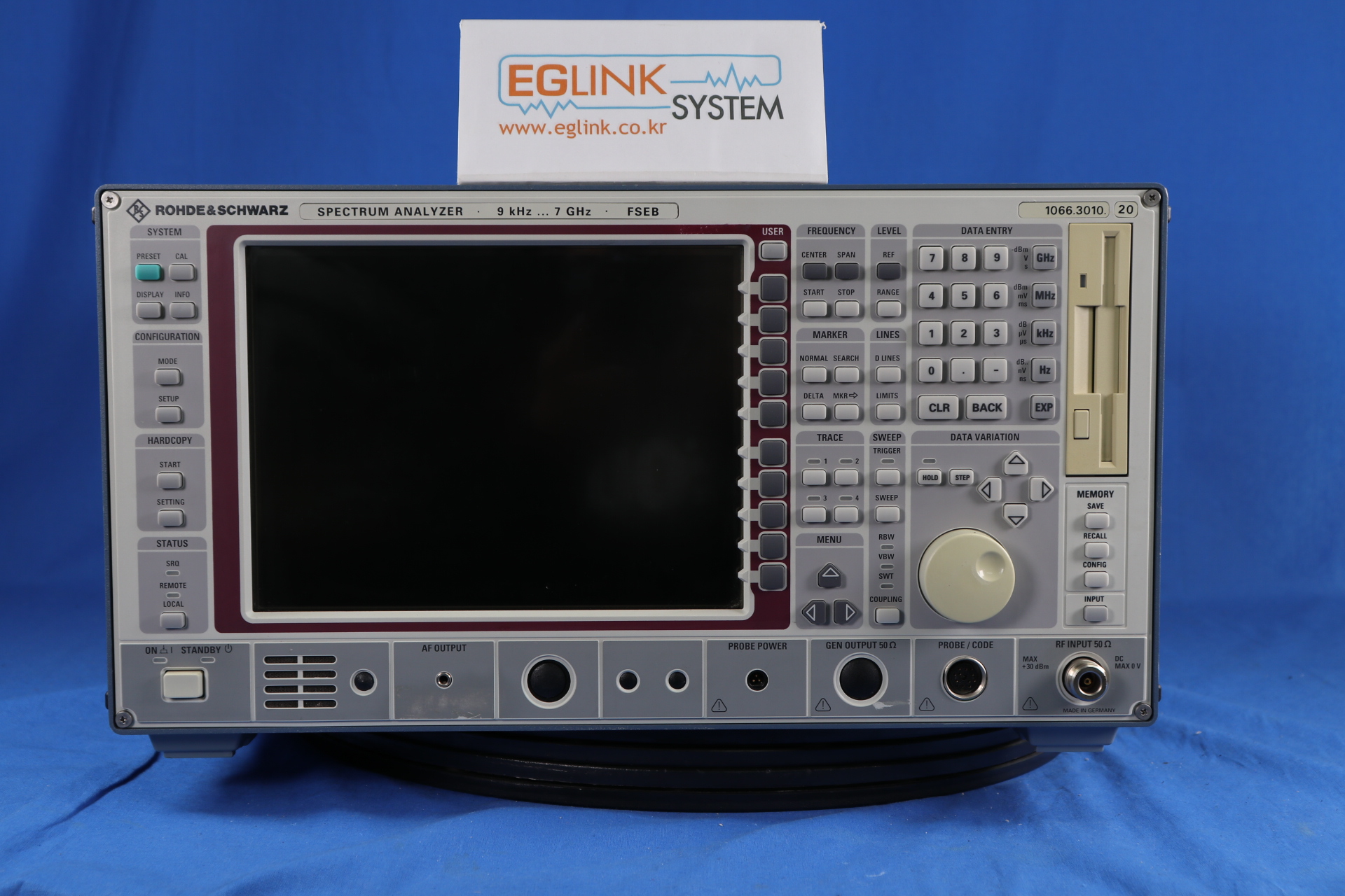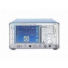
FSEB20 Rohde & Schwarz Spectrum Analyzer
Frequency Range: 9 kHz to 7 GHz
Input Impedance: 50 Ohm
Sweep Time: 1 us to 1500 sec
Resolution Bandwidth: 10 Hz to 10 MHz
Resolution Bandwidth Steps: 1/2/3/5
Video Bandwidth: 1 Hz to 10 MHz
Video Bandwidth Steps: 1/2/3/5 Single-Side-Band
Maximum Single-Side-Band Noise: -129 dBc/Hz to -79 dBc/Hz
Displayed Average Noise: -139 dBm to -84 dBm
Maximum Dynamic Range: 152 dB
Trigger Source External, Internal Freerun, TTL
Demodulation AM, FM
REQUEST A QUOTE
FSEB20 Rohde & Schwarz Spectrum Analyzer
B4: Low Phase Noise and OCXO /
B7: Vector Signal Analyzer /
B5: FFT Filter /
Detail
Additional Features:
Frequency Range: 9 kHz to 7 GHz
Input Impedance: 50 Ohm
Sweep Time: 1 us to 1500 sec
Resolution Bandwidth: 10 Hz to 10 MHz
Resolution Bandwidth Steps: 1/2/3/5
Video Bandwidth: 1 Hz to 10 MHz
Video Bandwidth Steps: 1/2/3/5 Single-Side-Band
Maximum Single-Side-Band Noise: -129 dBc/Hz to -79 dBc/Hz
Displayed Average Noise: -139 dBm to -84 dBm
Maximum Dynamic Range: 152 dB
Trigger Source External, Internal Freerun, TTL
Demodulation AM, FM
The Rohde & Schwarz FSEB20 spectrum analyzer is a wide band, very sensitive receiver. It works on the principle of "super-heterodyne receiver" to convert higher frequencies (normally ranging up to several 10s of GHz) to measurable quantities.
The received frequency spectrum is slowly swept through a range of pre-selected frequencies, converting the selected frequency to a measurable DC level (usually logarithmic scale), and displaying the same on the CRT. The CRT displays received signal strength (y-axis) against frequency ( x-axis).
Option
| Option |
Description |
| B15 |
Controller |
| B16 |
Ethernet Interface |
| B17 |
2nd IEC/IEEE-Bus Interface for FSE |
| B21 |
External Mixer |
| B4 |
Low Phase Noise and OCXO |
| B5 |
FFT Filter |
| B7 |
Vector Signal Analyzer |
| B9 |
Tracking Generator with I/Q Modulator |
Download
Video