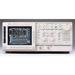
AWG510 Tektronix Arbitrary Waveform Generator
Single CH, 1GSa/sec, 4Mpoints/ch Record Length, 8 bit Vertical Resolution, 2Vp-p Output Voltage
REQUEST A QUOTE
AWG510 Tektronix Arbitrary Waveform Generator
Detail
Additional Features:
One Channel with 10-bit Vertical Resolution
External Clock Input Permits Jitter Insertion and Synchronization
10-Channel, 1 GHz Digital Data Generation (Opt. 03)
Real-time Noise Generation
Supports Direct External Clock and 10 MHz Reference Input
Waveform Transfers from DSO
File Transfers from GPIB, Floppy Disk, or 10Base-T Ethernet
On-Screen Waveform Editing for Ease-of-Use
Unique Real-time Sequencing Links Multiple Waveform Files Creating Waveforms of Nearly Infinite Length
Built-in 3 GB Hard Drive for Mass Data Storage
User Modified Isolation Pulse for Disk Drive Testing
Optional 78 MB Flash Disk for ATE Applications
Applications
Communications Design and Test:
Low Frequency Modulated RF
Digital Information Encoding Using FSK, PSK and QAM (Quadrature Modulation) for Cellular, Fax and
Modem Communications
Optical Communications Design and Test:
Reflections, Crosstalk, and Ground Bounce Simulation
Real-world Simulations:
Corrupt Ideal Waveforms
Add Jitter to Waveforms with Jitter Editor
EMP/EMI and Other System Noise
Power Supply Noise and Ripple
Transducer Simulation
As a member of the Tektronix family of arbitrary generators, the AWG 500 Series is a high performance, mixed-signal source. The AWG 500 Series provides 1 GS/s sample clock rate and 4 M word execution memories.
Its unique design integrates a graphical editing display with the most powerful hardware output capabilities available. This allows on-screen viewing of waveform editing and simplifies "what-if" test scenarios by easily allowing the creation of composite signals.
The AWG 500 uses a graphical user interface to overcome the historical difficulties associated with developing arbitrary and complex waveforms. Several intuitive and powerful techniques are built-in to develop and edit custom waveforms.
The standard AWG 510 configuration provides up to 2 V output or 4 V into a differential input with the complementary output, each with 10-bits vertical resolution. Option 03 adds an independent 10-bit-wide digital data port which can be used in conjunction with the marker outputs for data generation up to 12-bits wide at up to 1 GHz.
Option
| Option |
Description |
| 3 |
Channel 2 10-Bit Output up to 1 GHz |
Download
Video

