TOP
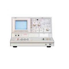
371A Tektronix Curve Tracer
Additional Features:  Fully Programmable Digital Curve Tracers with Cursors and Hardcopy High Voltage and Current Sourcing with the 371A Metrics Software and LabView Drivers Available to Enhance Operation CE Certified The 370-series digital curve tracers offer several advantages over analog curve tracers: Higher voltage and current sourcing capability (up to 3000 V and 400 A) Higher resolution voltage and current measurements (down to 1 pA and 50 μV) View a family of curves without flicker Display a reference curve to measure variations due to temperature, etc. Voltage, current, DC beta, and slope measurement with built-in cursor measurements Store curves and setups for consistent tests and measurements based on reference curves Full-color printouts using an HPGL plotter instead of expensive Polaroids Automate tests with computer and software (e.g., Metrics, LabView, etc.) High Current: 250 s pulses with maximum peak of 30 V. High Voltage: Full rectified sine with maximum peak of 3000 V (positive and negative polarities for both modes) Peak Voltage: 30 V +10%, –5%; Peak Current: 400 A; Maximum m Power: 3 kW Peak Voltage: 30 V +10%, –5%; Peak Current: 40 A; Maximum m Power: 300 W High-Voltage Mode: Peak Voltage: 3 kV +10, –0%; Peak Current: 40 mA ±20%; Maximum m Power: 30 W Peak Voltage: 3 kV +10, –0%; Peak Current: 4 mA ±20%; Maximum m Power: 3 W Peak Voltage: 300 V +15%, –0%; Peak Current: 4 mA ±20%; Maximum m Power: 300 mW Peak Voltage: 300 V +15%, –0%; Peak Current: 0.4 mA ±20%; Maximum m Power: 30 mW Polarities: NPN+: Positive; NPN–: Negative. Variable Collector Supply Range: Continuously variable from 0% to 100% in 0.1% resolution. Pulsed Collector Supply Pulse Width: 250 μs 10%. Pulsed Collector Repetition Rate 3 kW: 0.25 times line frequency. 300 W: 0.5 times line frequency. Loop Compensation (High Voltage mode): Stray capacitance between collector terminal and ground is compensated for up to a maximum of 100pF. Circuit Breakers: Both the high-voltage and the high-current supplies have breakers which operate independently. The high-current output breaker opens automatically in an over-current condition. Both breakers can be operated manually. 3 kW maximum: 1 A/div to 50 A/div. 300 W maximum: 500 μA/div to 5 A/div. 30 W maximum: 100 μA/div to 500 μA/div. 3 W, 300 mW maximum: 10 A/div to 500A/div. 30 mW maximum: 1 μA/div to 50 μA/div. Accuracy – Within 0.1 vertical division. Cursor Accuracy (nonstore mode, window cursor) – Readout X 2% plus 0.2 div of vertical setting. 3 kW, 300 W maximum: 100 mV/div to 5V/div. 30 W, 3 W maximum: 50 V/div to 500V/div. 300 mW, 30 mW maximum: 5 V/div to 50V/div Step Generator Voltage Range (VBE): 100 mV/div to 5 V/div (in increments of 1-2-5). Accuracy: Within 0.1 horizontal division. Cursor Accuracy (nonstore mode, window cursor): Readout times 2% plus 0.2 div of the horizontal setting. Step Generator Current Mode–High-Current (pulsed) Mode: Step Range and Waveform: 1 mA/step to 2 mA/step pulse Maximum Current: Step/offset amplitude setting X 20, maximum 20 A at 2A/step Maximum m Voltage: 10 V ±20% High-Voltage Mode: Step Range and Waveform: 1 μA/step to 2 mA/step stairstep Maximum Current: Step/offset amplitude setting X 20, maximum 20 A at 2A/step Maximum m Voltage: 10 V ±20% Ripple, Noise: Step/offset amplitude setting X 1% plus 10 nA. Pulse Width (collector supply high-current mode, 1 mA/step step/offset amplitude setting): 500 s ±10%. Voltage Mode High-Current (pulsed) and High-Voltage Mode: Step Range and Waveform: 200 mV/step to 5 V/step stairstep Maximum Current: 100 mA +50%,–20% Maximum m Voltage: Step/offset amplitude setting X 20, maximum 50 V. Ripple, Noise: Step/offset amplitude setting X 1% plus 10 mV, Number of Steps: 0 to 10 except 0 to 5 for the 5 V/step and 2A/step ranges. Step Polarity: Same as collector supply polarity. Reverse with STEP-INVERT button. Step Rate Pulse: 0.25 X the line frequency at 3kW, 0.5 X the line frequency at 300W. Stairstep: 2 X the line frequency. Offset: 0 to 10 X the step/offset amplitude setting with 1% resolution except 0 to 5 X at 5V/step and 2A/step settings. Polarity is same as the step signal. Test Fixture: Designed to allow easy connection to a variety of devices. Includes an integral safety enclosure to assure operator protection. Special patch cords are provided for connecting large devices. Metrics Software Recommended Computer Configuration: Minimum processor: 386DX/33 MHz IBM compatible computer. Free memory: 8 Mb minimum. Disk space: At least 14 Mb. Floppy drive: 1.44 Mb 3.5-inch. Operating system: Microsoft Windows 3. Interface cards: National Instruments GPIB card. Operating parameters can be adjusted, stored, and recalled using several storage methods including the 370A/371A non-volatile memory, the built-in DOS compatible floppy disk, or to an external GPIB controller. Metrics ICS can make measurements that are not available on a manually operated instrument, including the ability to sweep any supply. Extensive data management capabilities include project files, data export, DDE links, and search capabilities. Metrics ICS built-in automation capabilities include conditional pass/fail testing and result logging.
REQUEST A QUOTE
Stock
|
Detail
|
Option
|
Download
|
Video
Detail
Additional Features:  Fully Programmable Digital Curve Tracers with Cursors and Hardcopy High Voltage and Current Sourcing with the 371A Metrics Software and LabView Drivers Available to Enhance Operation CE Certified The 370-series digital curve tracers offer several advantages over analog curve tracers: Higher voltage and current sourcing capability (up to 3000 V and 400 A) Higher resolution voltage and current measurements (down to 1 pA and 50 μV) View a family of curves without flicker Display a reference curve to measure variations due to temperature, etc. Voltage, current, DC beta, and slope measurement with built-in cursor measurements Store curves and setups for consistent tests and measurements based on reference curves Full-color printouts using an HPGL plotter instead of expensive Polaroids Automate tests with computer and software (e.g., Metrics, LabView, etc.) High Current: 250 s pulses with maximum peak of 30 V. High Voltage: Full rectified sine with maximum peak of 3000 V (positive and negative polarities for both modes) Peak Voltage: 30 V +10%, –5%; Peak Current: 400 A; Maximum m Power: 3 kW Peak Voltage: 30 V +10%, –5%; Peak Current: 40 A; Maximum m Power: 300 W High-Voltage Mode: Peak Voltage: 3 kV +10, –0%; Peak Current: 40 mA ±20%; Maximum m Power: 30 W Peak Voltage: 3 kV +10, –0%; Peak Current: 4 mA ±20%; Maximum m Power: 3 W Peak Voltage: 300 V +15%, –0%; Peak Current: 4 mA ±20%; Maximum m Power: 300 mW Peak Voltage: 300 V +15%, –0%; Peak Current: 0.4 mA ±20%; Maximum m Power: 30 mW Polarities: NPN+: Positive; NPN–: Negative. Variable Collector Supply Range: Continuously variable from 0% to 100% in 0.1% resolution. Pulsed Collector Supply Pulse Width: 250 μs 10%. Pulsed Collector Repetition Rate 3 kW: 0.25 times line frequency. 300 W: 0.5 times line frequency. Loop Compensation (High Voltage mode): Stray capacitance between collector terminal and ground is compensated for up to a maximum of 100pF. Circuit Breakers: Both the high-voltage and the high-current supplies have breakers which operate independently. The high-current output breaker opens automatically in an over-current condition. Both breakers can be operated manually. 3 kW maximum: 1 A/div to 50 A/div. 300 W maximum: 500 μA/div to 5 A/div. 30 W maximum: 100 μA/div to 500 μA/div. 3 W, 300 mW maximum: 10 A/div to 500A/div. 30 mW maximum: 1 μA/div to 50 μA/div. Accuracy – Within 0.1 vertical division. Cursor Accuracy (nonstore mode, window cursor) – Readout X 2% plus 0.2 div of vertical setting. 3 kW, 300 W maximum: 100 mV/div to 5V/div. 30 W, 3 W maximum: 50 V/div to 500V/div. 300 mW, 30 mW maximum: 5 V/div to 50V/div Step Generator Voltage Range (VBE): 100 mV/div to 5 V/div (in increments of 1-2-5). Accuracy: Within 0.1 horizontal division. Cursor Accuracy (nonstore mode, window cursor): Readout times 2% plus 0.2 div of the horizontal setting. Step Generator Current Mode–High-Current (pulsed) Mode: Step Range and Waveform: 1 mA/step to 2 mA/step pulse Maximum Current: Step/offset amplitude setting X 20, maximum 20 A at 2A/step Maximum m Voltage: 10 V ±20% High-Voltage Mode: Step Range and Waveform: 1 μA/step to 2 mA/step stairstep Maximum Current: Step/offset amplitude setting X 20, maximum 20 A at 2A/step Maximum m Voltage: 10 V ±20% Ripple, Noise: Step/offset amplitude setting X 1% plus 10 nA. Pulse Width (collector supply high-current mode, 1 mA/step step/offset amplitude setting): 500 s ±10%. Voltage Mode High-Current (pulsed) and High-Voltage Mode: Step Range and Waveform: 200 mV/step to 5 V/step stairstep Maximum Current: 100 mA +50%,–20% Maximum m Voltage: Step/offset amplitude setting X 20, maximum 50 V. Ripple, Noise: Step/offset amplitude setting X 1% plus 10 mV, Number of Steps: 0 to 10 except 0 to 5 for the 5 V/step and 2A/step ranges. Step Polarity: Same as collector supply polarity. Reverse with STEP-INVERT button. Step Rate Pulse: 0.25 X the line frequency at 3kW, 0.5 X the line frequency at 300W. Stairstep: 2 X the line frequency. Offset: 0 to 10 X the step/offset amplitude setting with 1% resolution except 0 to 5 X at 5V/step and 2A/step settings. Polarity is same as the step signal. Test Fixture: Designed to allow easy connection to a variety of devices. Includes an integral safety enclosure to assure operator protection. Special patch cords are provided for connecting large devices. Metrics Software Recommended Computer Configuration: Minimum processor: 386DX/33 MHz IBM compatible computer. Free memory: 8 Mb minimum. Disk space: At least 14 Mb. Floppy drive: 1.44 Mb 3.5-inch. Operating system: Microsoft Windows 3. Interface cards: National Instruments GPIB card. Operating parameters can be adjusted, stored, and recalled using several storage methods including the 370A/371A non-volatile memory, the built-in DOS compatible floppy disk, or to an external GPIB controller. Metrics ICS can make measurements that are not available on a manually operated instrument, including the ability to sweep any supply. Extensive data management capabilities include project files, data export, DDE links, and search capabilities. Metrics ICS built-in automation capabilities include conditional pass/fail testing and result logging.
Option
Option Description
371A Test Fixture
Download
Video