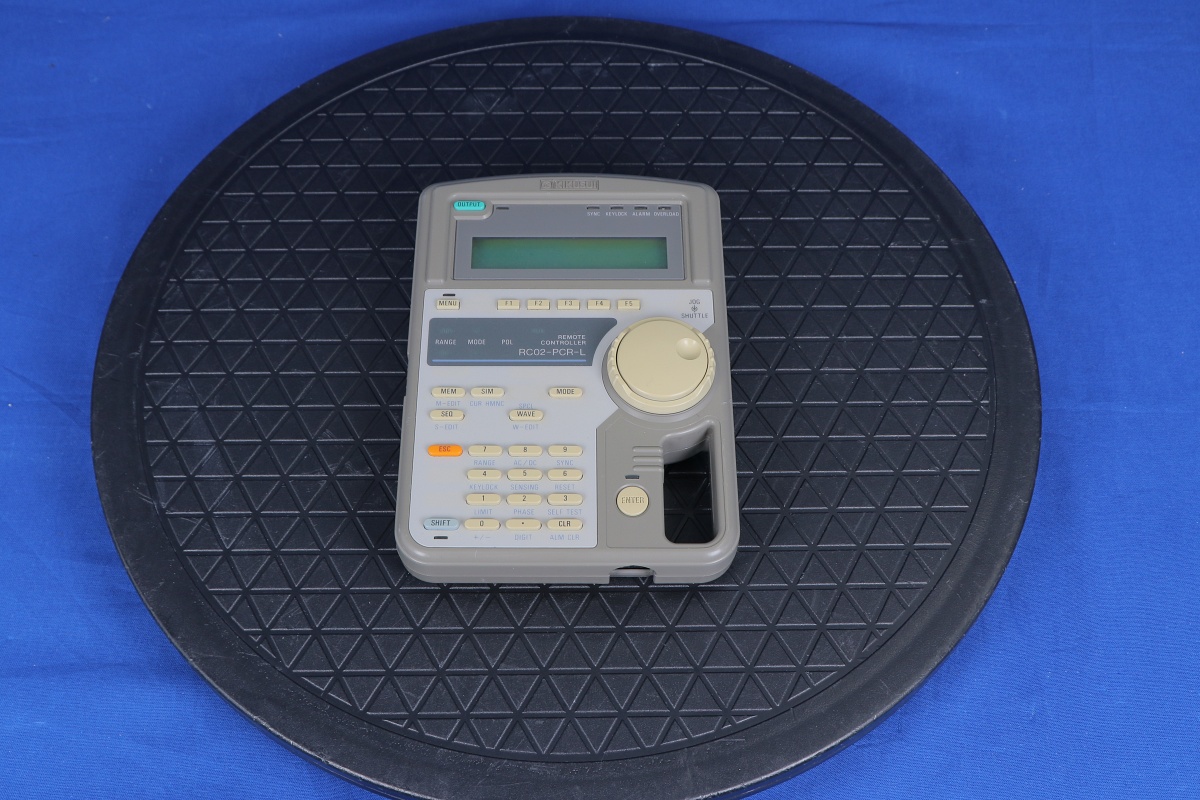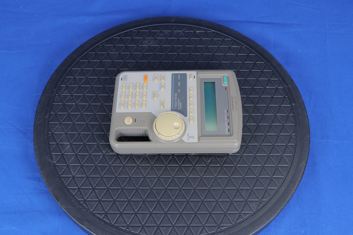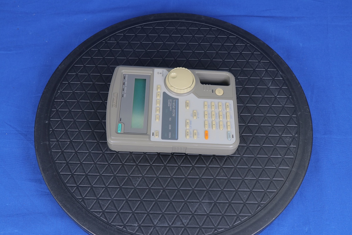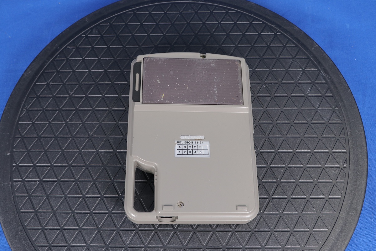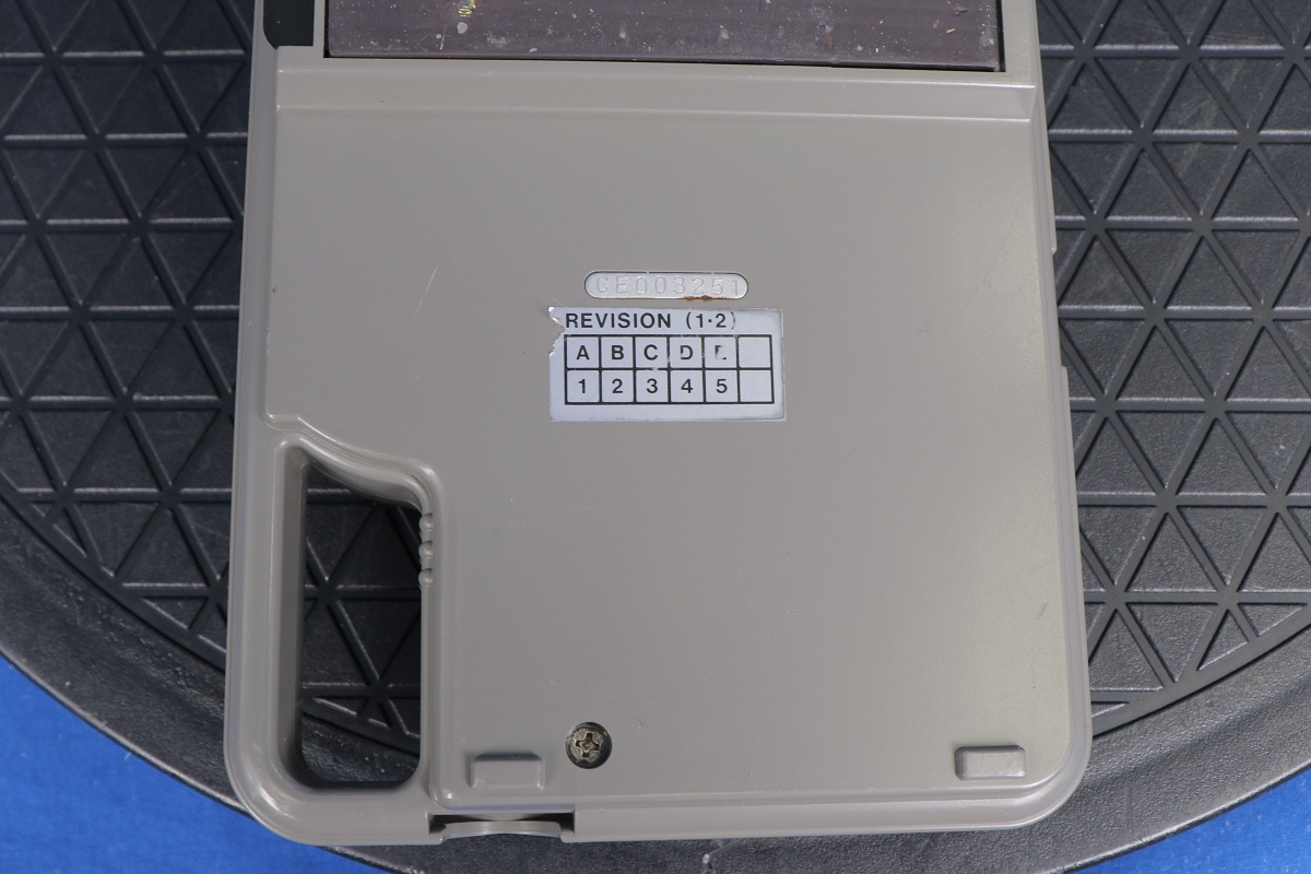
RC02-PCR-L Kikusui Interface
Additional Features:
Remote Controller for the PCR-L Series
Applicable Sot Numbers: 1, 2, 3
Optional Measuring Functions Available with the RC02-PCR-L:
Current: Peak hold value
Harmonic current: 1st to 39th harmonic
Electrical Power: Apparent electrical power, Power factor
The Kikusui RC02-PCR-L is a Remote controller for the PCR-L Series AC power supplies.
The remote controller allows each of the functions on the control panel of members of the PCR-L/LT series to be manipulated while away from the control panel. Moreover, this remote controller is composed of options for expanding functions, including harmonics current analysis, power line irregularity simulation and sequence operation, a remote controller box a remote controller card (inserted into a slot in the main unit) and a remote controller cable.
The function of the PCR-L series can be further expanded to include measurement and output waveform generation functions through the use of an optional remote controller and interface boards.
Functions Available using the RC02-PCR-L
GPIB Interface(IB11-PCR-L)
The GPIB interface for the members of the PCR-L/LT series allows programmable control of the functions on the power supply control panel as well as nearly all the expansion functions available by using the RC02-PCR-L remote controller. This interface also performs readout of measured values.
RS-232C Interface (RS11-PCR-L)
The RS-232C interface for the PCR-L/LT series allows readout of measured values and programmable control of the functions on the power supply control panel as well as nearly all the expansion functions available by using the RC02-PCR-L remote controller.
Power Line Abnormality Simulation
The equipment allows simulation of power failure, fast voltage drop (dips), or fast voltage rise (pops). This function is used to test switching power supplies or micro-processor-based devices.
Sequence Operation
Specifying sequence operation by combining output voltage and frequency or other factors with time setting allows automatic operation. This function can be used to automatically test a variety of devices and equipment.
Harmonic Current Analysis Function
Harmonic current analysis is available for output current from the equipment. The conventional approach used an FFT analyzer for measurement. In contrast, this equipment requires no FFT analyzer. This function can be used for harmonic current analysis of various equipment.
Special Waveform Output
This function allows the equipment to output any waveform other than sine waves. The "peak clipped waveform" in which the peak of a sine wave is suppressed is provided as standard. Also, if arbitrary waveform data is transferred to the equipment, the waveform can be output.
This function can be used not only for a variety of electronics devices but also for chemical experiments and production equipment.
Output Impedance Setting
The equipment has almost 0 Ω output impedance (output resistance); the actual commercial power line has several mΩ to several Ω impedance (resistance). When an optional device is connected, the equipment allows output impedance to vary. This allows simulation of the environment similar to actual commercial powerline.
This function is backed up inside the equipment. Therefore, once a setting is made using an optional device, the equipment can operate in the same condition continuously even if the option is removed, as long as the setting conditions remain the same. The function can be used to test various devices and equipment.
Measurements of Power-Factor, VA, and Peak Holding Current
The equipment has diverse measuring functions which can be extended using an optional product. These additional functions include the measurement of power-factor, VA, and the peak holding current.
With peak holding current measurement, the peak current is measured until the equipment receives a peak clear signal or command. This function is useful in measuring a rush current and can be used to test various devices and equipment.
Output ON/OFF Phase Setting
Output ON/OFF phase setting is available separately. This function is used when output ON/OFF phase setting is required. This function is backed up inside the equipment. Therefore, once setting is accomplished using an optional device, the equipment can operate in the same condition continuously with the option removed, as long as the setting conditions remain the same.
AC + DC Mode
This function allows the equipment to output voltage waveforms in which AC voltage is superimposed on DC voltage. The function can be used not only for various electronics devices but also in chemical experiments and for production equipment.
Expansion of the Memory Function
This equipment allows nine sets of voltage and frequency settings to be stored as standards in the memory (memory addresses 1 to 9), enabling the data to be read for output as necessary. When an optional product is attached, the equipment can accommodate a maximum of 99 sets of voltage and frequency set values for storage.
In the AC + DC mode, both AC and DC memory values can be output, allowing all the memory operations in the AC + DC mode.
Regulation Adjustment
With regulation adjustment, the output voltage is adjusted automatically to compensate the voltage drop caused by the output current.
This function is used for the same purpose as the sensing function. The sensing function measures the sensing point voltage in order to maintain a constant sensing-point voltage; with regulation adjustment, the voltage drop caused by the output current is calculated in order to raise the output voltage in an amount equivalent to the drop.
This function is used for stabilizing voltage at the load end if there is a considerable distance between the load and the equipment.
When regulation adjustment is performed, voltage stability accuracy, distortion factor, and response speed decrease. Therefore, this function may not be suitable depending on application. Check the specifications before use.
REQUEST A QUOTE
